The goal is to deliver stable uninterrupted power to GPUs, while minimizing overheads or faults.
Power comes in from the grid (can be produced on-site, but rare). Most of the time, the grid is not close-by, and power is transmitted as High Voltage (HV) AC with 3 phases. At the site, it is stepped down to Medium Voltage (MV) using a transformer.
The GPUs, interconnects, and other equipment will eventually need Low Voltage (LV), so either we can step it down to LV now, or do it when we get closer to the GPUs. Doing so at this stage would mean a very high current, which would then require a lot more copper wiring, insulation, and heat loss proportional to current squared, which makes this not so desirable. So the power remains at MV, and is routed around the campus in parallel using MV switchgear + bus and is only stepped down to LV near the data halls.
Close to the halls, there are MV-to-LV transformers coupled with generators containing Automatic Transfer Switch (ATS). This generator will function as a backup in event of a transformer failure, and its power rating typically matches that of the transformer. From here, the power is now in LV and is distributed using LV switchgear.
Everything in the power infrastructure is built with redundancy in mind to ensure reliability. For example, each data hall can be supplied by two different power sources, leaving no single point of failure.
From the LV switchgear, the power does not directly go to the server racks, but to an uninterruptible power supply (UPS) system. The UPS smooths out fluctuations, and bridges short power interruptions. This introduces small inefficiencies into the system, but its usually worth it as an insurance against sudden outages.
The UPS sends stabilized LV power into the Power Distribution System (PDUs) which decide which rack gets how much power. Power is split from larger cables into multiple smaller feeds for racks here. Again, 2N redundancy is pretty standard here.
In cloud datacenters, the PDU to rack connection was using flexible copper cables but for GPU racks busways are preferred. These are rigid copper or aluminum bars mounted overhead or under the floor. This minimizes clutter and reduces losses.
Two independent busways run the length of the room to connect the racks. At each rack, a tap-off unit connects the busway to the rack using a short flexible cable called a whip. So, every rack gets two independent whips, one from each busway.
Now we're finally at the rack level. Power enters through vertical PDUs (vPDUs) located on both sides of the rack. Each vPDU corresponds to one power feed. The servers and GPU trays are dual-corded, one cord for each power feed. Even if one side drops, the other can carry the load automatically. Sometimes there is a static transfer switch here, which makes this transition easier and more reliable.
There are a few power shelves at the rack level which convert the incoming AC to a shared DC busbar that runs across the rack. Each server sled clips into this DC busbar. These shelves can also contain Battery Backup units (BBUs) which are a mini-UPS system. But these days many DCs and racks (such as GB200) don't have these so as to save space.
Once DC power reaches the server itself, it's stepped down again inside each system. There are on-board converters and voltage regulator modules (VRMs) that supply the GPUs with extremely low voltage (<1V) but at very high current (100s of A). These VRMs must respond rapidly to power spikes from the workloads running on the GPUs and maintain a steady voltage overall.
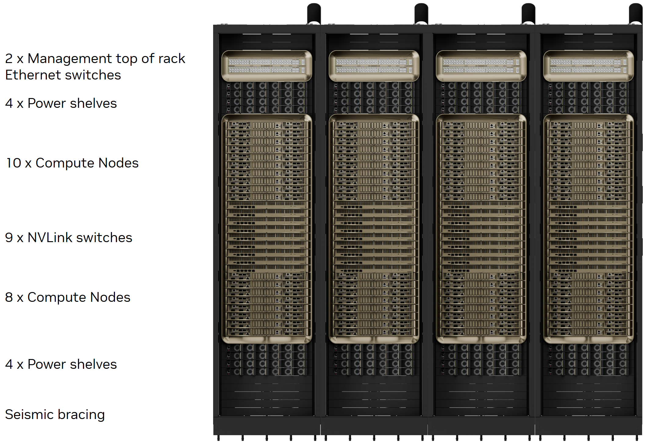
For visualization, here is a GB200 rack.
Example: Abilene Site for Stargate
Let's assume that the racks inside the data hall are all GB200s. A GB200 rack consumes about 120 kW and peaks at ~132 kW. This rack has 72 Blackwell GPUs + 36 Grace CPUs + NVSwitch + 8 power shelves (33 kW each- 2x for redundancy) + cooling equipment.
The campus is designed for ~1.2GW total power. The current site that is already online has 200 MW for two buildings.
From the grid, power comes in at 345 kV via a large greenfield substation. After it is stepped down, it is distributed using the MV switchgear at 34.5 kV.
Close to the data halls, there are MV to LV transformers feeding the LV switchgear. Abilene emphasizes campus-level resiliency instead of lots of diesel generators. They do this by having a 1000 MW battery system + an on-site 360 MW natural gas plant. Maybe they also have generators, but all this is to ensure extra reliability and no down time.
From here, both busways to a GB200 rack must be able to carry the full 132 kW requirement independently. At 415 V three phase, this leads to per feed current (worst case) of ~184 A per phase per feed. Each 33kW power shelf gets 46A per phase current. With ~1.0–1.2 kW per B200, we have 1.2 kW × 72 ≈ 86.4 kW (~65% of the 132 kW rack) for GPUs. So GPUs are ~65–75% of rack power. The rest goes to CPUs + interconnects + cooling overhead.
With these numbers, but assuming no inefficiencies or overhead, 200 MW supports ~1515 racks (110k GPUs), and a full 1.2 GW it's about 655k GPUs.
With a 1.09 PUE, or ~8.3% power going to cooling + overhead, 200 MW incoming power can support ~1390 racks (100k GPUs), and 1.2 GW campus would be able to support ~9000 racks (650k GPUs).